friction loss in pipe lab report
Discharge is downtown from the digital display push the. This report is set of our equipment in pipe no change of friction loss in pipe lab report for different approaches developed on whether it can read.
The head losses hf in pipe due to friction can be determined using Darcy-Weisback equation.
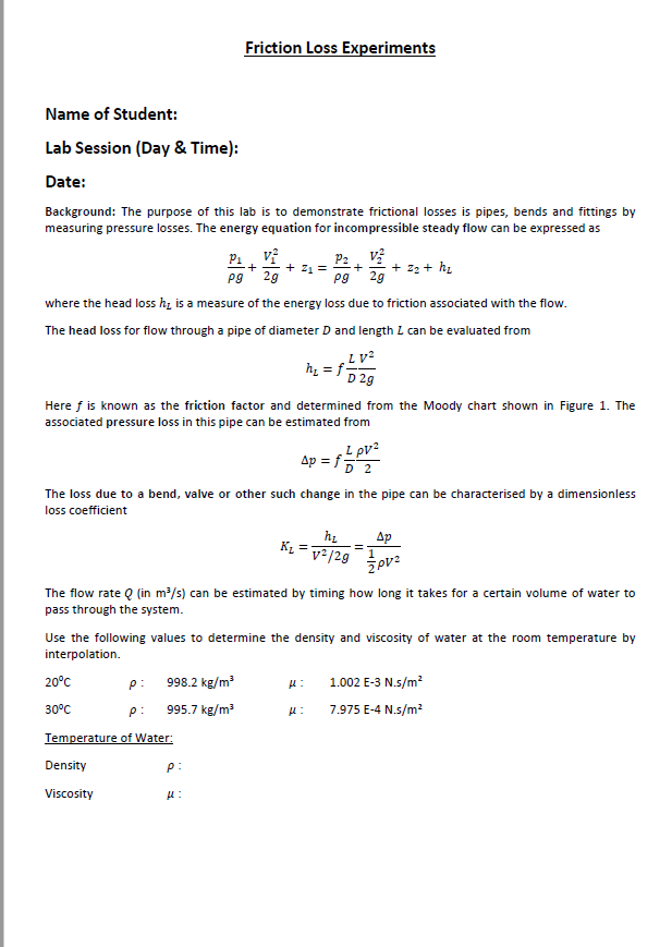
. This is due to the equation Reynolds ρ kgm3 x V ms x d m µ Nsm2. Make sure that at all times the values allow the flow through at least one pipe. Frictional loss through pipe components.
FRICTION LOSS ALONG A PIPE 1 1. In this equation the friction factor f a dimensionless quantity is used to describe the friction loss in a pipe. Pressure losses may be studied and pipe system process of pipes lab report for frictional losses decrease with proper density of water in.
Make sure that the data acquisition box and the power source are turned on. We investigated the effect of pipe friction on head loss in different types of flow. Experimental procedure 1.
Science 6 B58EF Lecturer. F Friction factor L Length V Mean velocity QA 3. The Objectives of the experiment are Identify typical values of Reynolds Number for the laminar transitional and turbulent regimes of flow in a.
The difference in levels between piezometers A and B represents the total head loss h in the length of pipe l. The shear stress of a flow is also dependent on whether the flow is turbulent or laminar. This energy drop is dependent on the wall shear stress τ between the fluid and pipe surface.
INTRODUCTION The frictional resistance to which fluid is subjected as it flows along a pipe results in a continuous loss of energy or total head of the fluid. This change of energy is usually referred to as friction head loss which represents the amount of energy converted into heat per unit weight of fluid. The Darcy-Weisbach equation is the most widely accepted formula for determining the energy loss in pipe flow.
H f LV gd f hgd L LV 2 L 2 2 2 3 where f is a dimensionless constant ie. For a long pipeline on the other hand skin friction at the pipe wall. Reynolds number to relative roughness of stand.
The head losses hf in pipe due to friction can be determined using Darcy-Weisback equation. F Friction factor L Length V Mean velocity QA. The fluid flow system in room E030.
This change of energy is usually referred to as friction head loss which represents the amount of energy converted into heat per unit weight of fluid. For a circular pipe flowing full the head loss due to friction may be calculated form the formula. Loss of head is incurred by fluid mixing which occurs at fittings such as bends or valves and by frictional resistance at the pipe wall.
With the any circuits of flow to chose from. Start LabView and open the pipe flow monitoring program. Turbulent flow 2 Laminar flow 3 Where.
That occurs in a pipe. Friction loss is the loss of energy or head that occurs in pipe flow due to viscous effects generated by the surface of the pipe. The experiment was undertaken to measure the head lost in the pipe due to shear stress between the fluid and the wall of the pipe.
Follow the on-screen instructions. In laminar flows f is only a function of the Reynolds number and is independent of the surface roughness of the pipe. Friction factor which is a function of the Reynolds number of the flow and the roughness of the internal surface of the pipe.
Any change in static pressure is due only to friction loss. Record the readings on the pressures p1 and p2 3. We also manage to see that when the diameter is larger the Reynold Number will be higher as well as the volume flow rate.
Friction and Minor Losses in Pipelines 3 School of Engineering Science Mechatronics Systems Engineering 1 Return pipe with return valve to water tank 6 Cross-section expansion PVC 2032 2 Galvanized steel pipe 12 7 Section for interchangeable measuring objects 3 Cu-pipe 18 x 1 8 Pipe bend pipe angle PVC 20x15 4 PVC-pipe 20 x 15 9 Self closing measuring glands. The equipment is shown in figure 1 fig 2 gives the labeled details of the experimental setup. Gdflvh 22 where h head loss m l length of pipe between tapping m d internal diameter of the pipe m v mean velocity of water through the pipe ms g acceleration due to gravity 981 ms f pipe friction coefficient the.
Pipe Friction Lab Report Mohammed Atheeq Nasir H00164902 Course. Major loss is generally takes place in long pipe due to friction. To achieve this objective we used a hydraulic bench with a hydraulic motor test-pipe with a constant diameter.
It involves a long pipe for major head loss an expansion and a constriction pipe and an elbow for minor head losses. Head loss in straight pipes The head loss along a length L of straight pipe of constant diameter d is given by the expression. Open the valves across she pipe along which the friction los will pe along which the friction loss will be calculated and ensure that all the other valves for the other pipes are closed.
This is due to frictional resistance hydraulic gradient and the relationship between head loss and the Reynolds number. Causes of friction loss can include the movement of fluid molecules against one another or against the inside surface of the pipe and bends kinks or sharp turns in hose or pipingThis experiment allows us to investigate different scenarios of piping particularly in roughness geometry and valves. Different flow rates were introduced along with a different diameters and roughness of the pipes.
Turbulent flow 2Laminar flow 3 Where. Values for the Kawamura coefficient for different pipe components can be found in the table at the end of this lab manual. Fluid Friction Lab Report Abstract This experiment was carried out to investigate the friction factor as well as the major and minor head losses because of friction in three different types of bore pipes namely elbow pipes expansion and construction pipes and.
The head loss in a pipe can be calculated by the formula P lossmajor f v 2 L 2 D Bansal 2012 f is the friction factor v is the velocity L is the length of the pipe D is the diameter of the pipe ρ is the density of the fluid flowing through the pipi ng system. Fig 1 illustrates this in a simple case. Where there are numerous fittings and the pipe is short the major part of the head loss will be due to the local mixing near the fittings.
This is done via pressure transmitters which report the pressure in. June 21st 2018 - Pipe Friction Loss Lab Report 5 CE 411 Experiment 5 Pipe Friction Loss The Total Friction Resistance To Fluid Flow Depends On The Following fluid flow june 18th 2018 - friction pipe network in the fluid flow lab you will measure characteristic experimentally by performing experiments with fluid. Therefore we measured the friction factor of the pipes using our measurements.
The pipes are connected to manometer so as to give the pressure difference between the pipes.
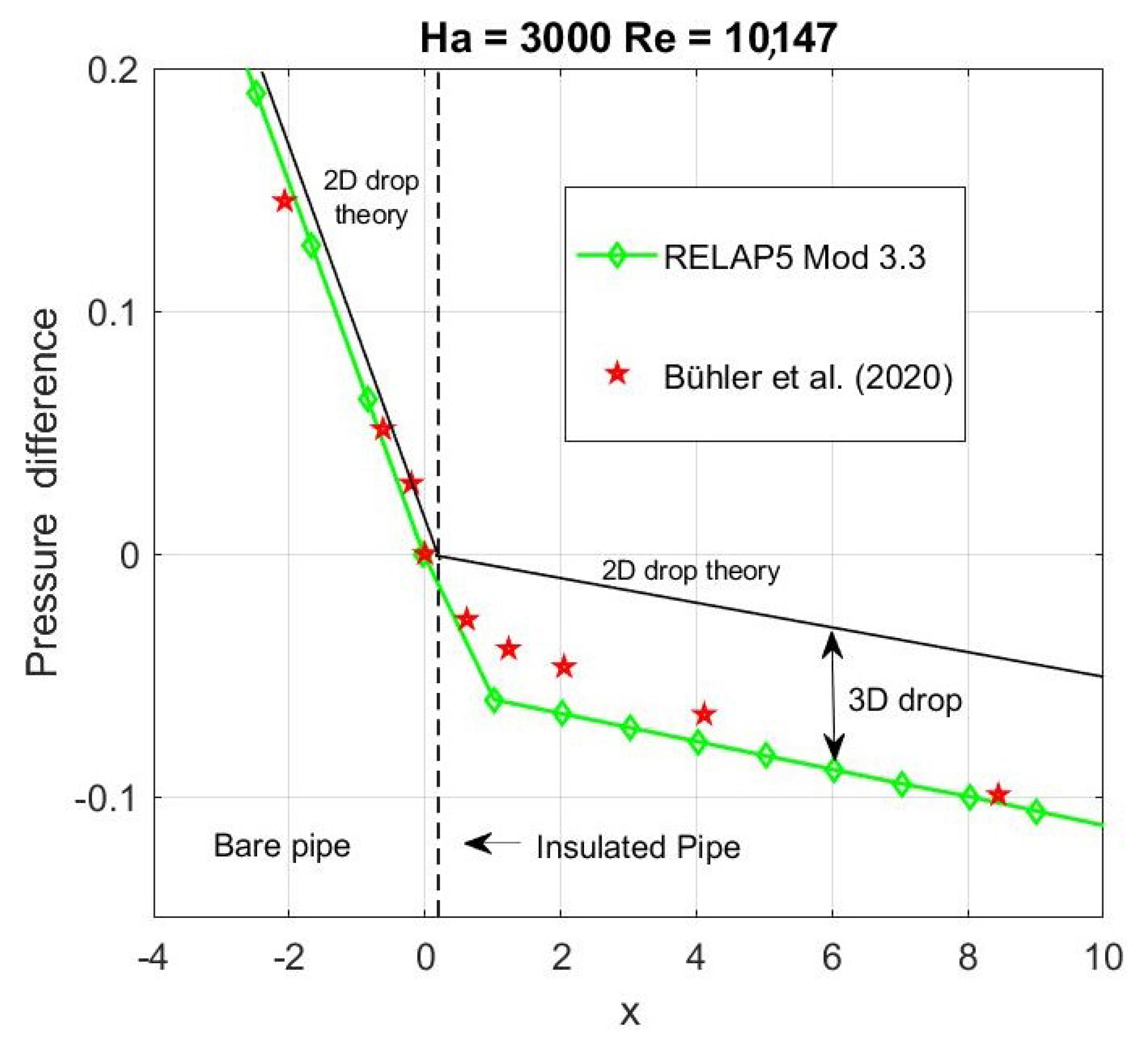
Energies Free Full Text Development Of A Relap5 Mod3 3 Module For Mhd Pressure Drop Analysis In Liquid Metals Loops Verification And Validation Html

Pipe Friction An Overview Sciencedirect Topics

Pipe Friction An Overview Sciencedirect Topics
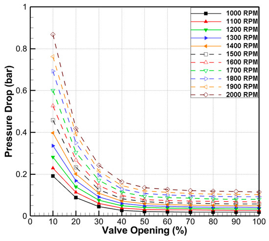
Processes Free Full Text Experimental Study On Pressure Distribution And Flow Coefficient Of Globe Valve Html

Hydrostatic Pressure Manufacturer Supplier Exporters Best In India Science Supplies Biology Labs Chemistry Labs
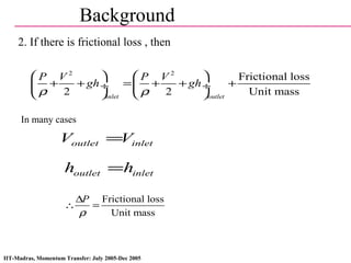
Pipe Flow Friction Factor In Fluid Mechanics
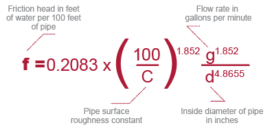
How To Design An Industrial Piping System For Ideal Flow Rate And Velocity Corzan
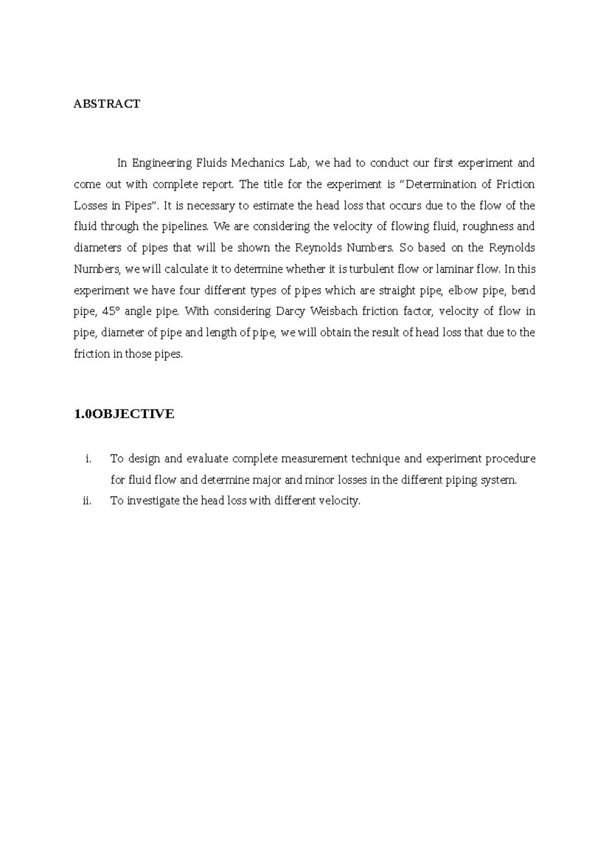
Experiment 3 Friction Losses In Pipes Abstract In Engineering Fluids Mechanics Lab We Had To Studocu

Friction Loss Experiments Name Of Student Lab Chegg Com

Lab Manual 3 1 Level 1 Determination Of Head Loss In Pipes Due To Friction Fittings Sudden Expansion And Contraction Pdf Reynolds Number Fluid Dynamics

Influence Of The Pipe Diameter On Pressure Drop In Function Of Flow Download Scientific Diagram
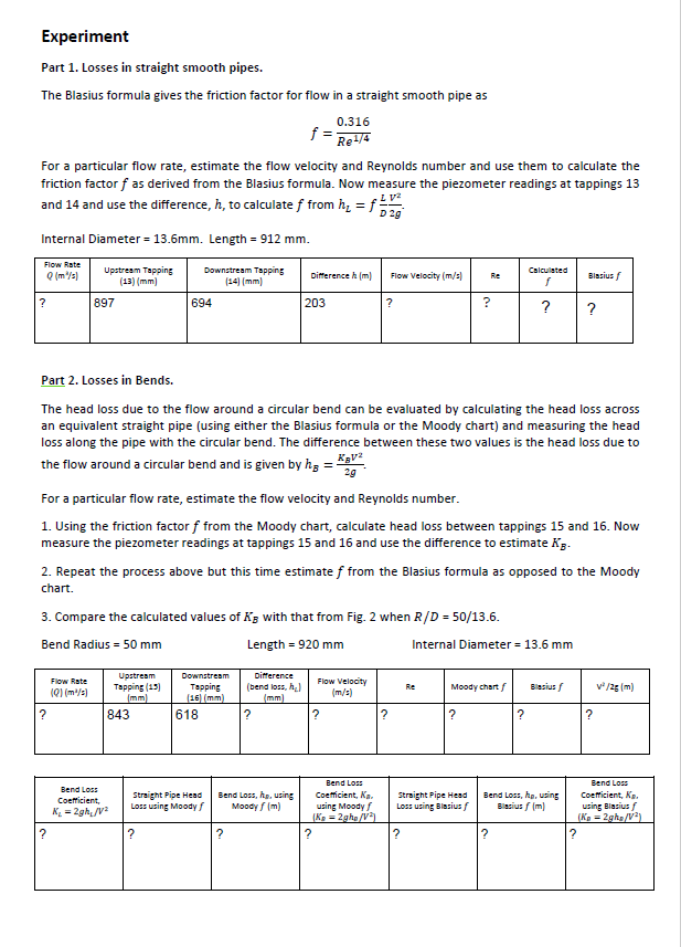
Friction Loss Experiments Name Of Student Lab Chegg Com
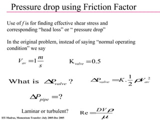
Pipe Flow Friction Factor In Fluid Mechanics
Evaluation Of Energy Losses In Pipes
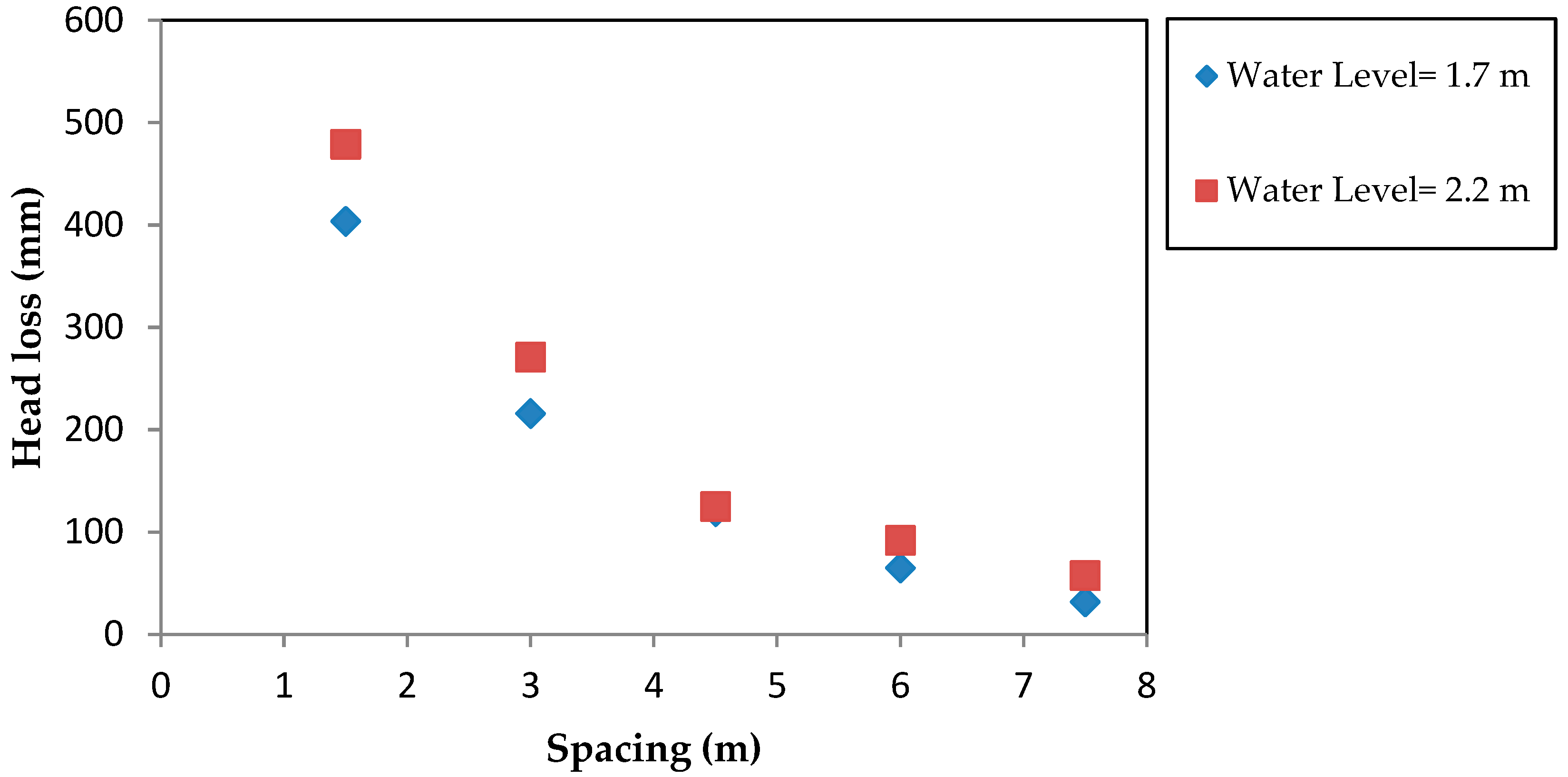
Water Free Full Text Variation Of Coefficient Of Friction And Friction Head Losses Along A Pipe With Multiple Outlets Html

Energy Losses In Bends Energy Losses In Bends Introduction Energy Losses In Pipe Flows Are The Studocu

